
SECURITY SOLUTIONS >> BURGLAR ALARM >> SECURITY ALARM SYSTEM
This burglar alarm system circuit is using a infrared proximity detector that triggers an alarm when the rays falling on its sensor are interrupted. It is different from others burglar alarm systems because is a very simple diy project and can offer you great satisfaction.
The circuit of IR burglar alarm system comprises transmitter and receiver-cum-alarm sections. It works off 6V DC, 500mA uninterrupted supply and uses low-cost readily-available electronic components. LED2 is used for indicating power-on. Check out the Infrared alarm circuit too.
Burglar alarm circuit diagram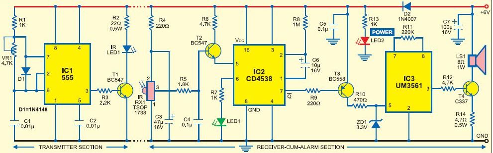
The transmitted IR signal directly falls on IR sensor TSOP1738. Whenever the IR signal is interrupted, its output pin 3 goes low and IC2 is triggered at pin 5 through transistor T2. As a result, its output at pin 7 goes low (for a preset time) to forward bias siren-driver transistor T2. This condition is indicated by the glowing of LED1. The time-out period can be increased or decreased by changing the value of capacitor C6.
The output tone of siren-sound generator IC3 can be set by connecting its pin 6 to either Vcc or GND.
When you connect pin 6 to Vcc IC3 produces the sound of fire-alarm siren, but when you connect it to GND it produces the sound of ambulance siren.

